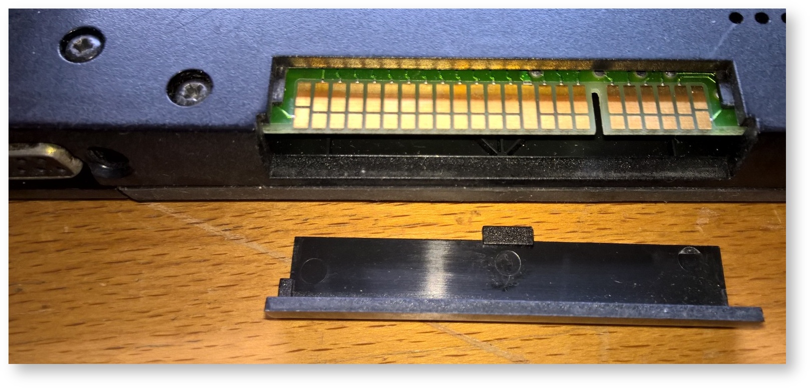
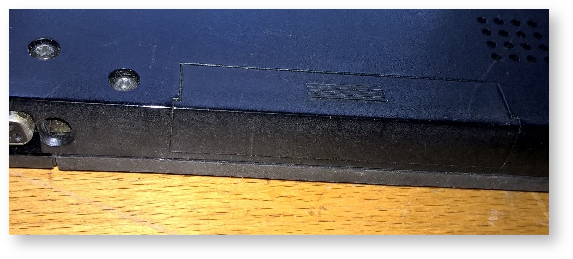
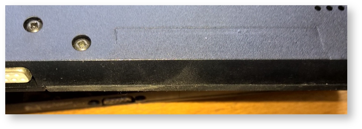
The expansion port connector
| Early Z88 Models - with the connector | |
|---|---|
| Z88 connector with flap removed | Z88 connector with flap in place |
 |  |
| Later and Current Z88 Models - without the Connector | |
| Z88 PCB connector pads tinned (no gold). | The Z88 case moulding is changed - no flap. |
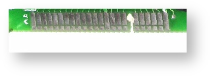 |  |
To our knowledge, this was never used with any external device. Earlier models had a removable flap to expose the standard 2.54mm double sided gold plated 48 pins male connector that presented all the Z80 bus signals.
On later models, when it was discovered that using this connector caused the Z88 to be unstable, the flap was made part of the case and the connector pads on the PCB were tinned, no longer gold plated.
Component       P C B
Side A Edge     Side B
GND     1       SNSL see below
A11     2       +12v
A12     3       A10
A13     4       A9
A14     5       A8
A15     6       A7
clock   7       A6
D4      8       A5
D3      9       A4
D5      10      A3
D6      11      A2
VCC     12      A1
D2      13      A0
GND     14      GND
D0      15      D7
D1      16      M1L
INTL    17      FLP (flap switch)
slot    18      slot
HALTL   19      NMIL
MREQL   20      WRL
IORQL   21      RDL
MAWL    22      RESETL Resets Z88 (2 pulses required)
-BT     23      SVCC 5.4v while the machine is 'on.'
GND     24      SNSL
SNSL allows the machine to be automatically placed into comatose state buy causing a 'power fail interrupt' when an edge connector is plugged into to the expansion slot of the Z88.