Design Considerations
TinyCAD
To build this device, the circuit needs to be redrawn reflecting any changes that have may need to be made to the original.
TinyCAD has been used for this purpose. It can also produce the
- Parts List and
- Net List
which are used by subsequent software to plan the final layout.
Checking the Circuit
The original circuit from the manual was checked against the new circuit diagram. The new circuit diagram will be constantly updated during the development of the design. This means that this initial drawing will be different to the final result.
 |  |
Circuit Changes
The regulator is no longer available. The LM317 device is an equivalent. It is a 3 pin device rather than a 5 pin. The differences are as follows:
Signal | SGS L200 | LM317 |
|---|---|---|
| INPUT | 1 | 2 |
| LIMITING | 2 | N/A |
| GND | 3 | N/A |
| REFERENCE | 4 | 1 |
| OUTPUT | 5 | 3 |
http://www.science-bbs.com/69-electronics-design/fc5ada8f79fdedb9.htm
The Diode D2 has been replaced by a later version.
PCB or Stripboard
Size (mm) | Size (in) | Area (in2) | ||
|---|---|---|---|---|
| 100 x 60 | 3.93 x 2.36 | 9.27 |
Company | Notes | 1 | 2 | 3 | Delivery | |
|---|---|---|---|---|---|---|
| PCB Train | 44.10 | 71.66 | 82.69 | 5.00 | ||
| Olimex | ||||||
| $5 per square inch for 3 copies of design. $46.37 | 28.67 | |||||
| PCB Cart | 5 pcs. of a 2 layer 50mm x 50mm board silkscreen legend on both sides cost about 80$ (8$ / pcs. + 1 time tooling costs of 40$). Shipment costs are between 20$ ad 30$ | |||||
10cm x 10cm dual layer, 2xsoldermask 2xsilkscreen $28,00 |
It is not worth building a PCB at this stage.
Designing the Prototype Layout
There are several layout programs available.
I am already using a TinyCAD schematic editor so I should be able to use VeeCAD with no problems.
Changes to some Resistor Values
The meter in the battery tester may be of a different type than the one described in the service manual circuit.
On the 3v setting of the battery the following resistors are used.
R12 + R7+ R6 = 690 + 1500 + 910 = 3100
V / R = I
3 / 3100 = 97 mA
On the Z88 circuit I am not sure what the calculations should be. A variable resistor will be used initially to set the full scale deflection on the meter. This value will determine the values of R1 and R2 before they are soldered onto the strip board.
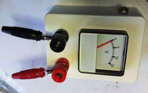
Terminals
The lead from the unit to the Z88 batteries need to be 'unplugged.' The test leads supplied with the battery tester are currently fixed. It is proposed to replace the 'button cell' terminals with Black and Red terminals so that the lead may be disconnected. The probes supplied will also be discarded.
Dummy Batteries
 |  |
The other unusual part to get is a set of dummy batteries. This allows the test leads to be connected to the battery connections inside the Z88. This battery set assumes that AAA size batteries are to be used. The size of these are 44 mm long x 10mm Diameter. These can be made up from M5 screws, nuts with metal and plastic washers,
Switches
| No | Switch detail | Instruction |
|---|---|---|
| SWA | Normally Pos 3 3 - on 2 - off - mom 1 - mom | Set switch A on the test box to position 2 and release. Set switch A on the test box to position 1, and hold. Check that Release switch A and check: |
| SWB | Set Switch B on the test fixture to position 2 (jack). Set switch B on the test box to position 1 and check that the display | |
| SWC |
| Operate switch C and hold. Release switch C. |
| SWD | Push to break | Press and hold switch D for approximately 1 second. |
Using VeeCAD
What I should have done first was to specify the size I wanted before designing the layout. However this is a chicken and egg process.
- I first designed the layout to get used to the package.
- The design would not fit in the space required.
- A paper template was used, cutting a hole for the meter and indicating where the fixing screws were.
- I then redesigned the layout.
- Strip board size
It is quite important before doing the design on the strip board that the correct size and that the areas where the fixing holes are known. A paper template was used and cut until it fitted the available space in the meter box. The template was measured and the fixing holes marked. The size and areas not available for components are marked on the planning board.
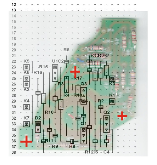
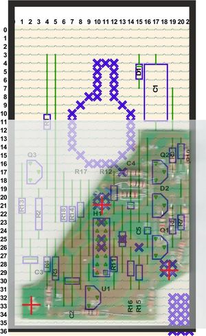
First Results
The first results are shown here, overlaid with the original battery tester board.
- The cuts in the strip-board are not shown.
- The Meter is in the curved section at the top.
- The RED crosses indicate the fixing holes which are kept clear of components.
- Components are also used in an area that the original board did not occupy.
Points arising
- Rather than using individual pins to connect the wires to the strip board it was decided to use a 14 way header plug and ribbon cable.
- The current of 500mA from the Z88 is too high for 1 core of 28 AWG. Two cores are used for both power in and power out.
- I should have bought the VeeCAD package straight away. It has automatic routing which is quick.
There is no standard for describing component sizes or which pin goes where. The 'Package' field of each component in Tinycad is used by VeeCAD for the size of the component to be used on the strip board. A new field (Type) is added in Tinycad. This is the type of component described in the manufacture's technical data sheet. They are as follows:-
| Package | Type | Package | Type | Package | Type |
|---|---|---|---|---|---|
| AX2_1N | CFR16 | AX2_1N | LR0204 | TO-92 | TO92 |
| TO-92A | TO-92A | AX2_1 | DO-35 | AX1_1 | SR21 |
| AX4_1N | LR1 | AX1_2N | 0805 | AX3_1N | CRF25 |
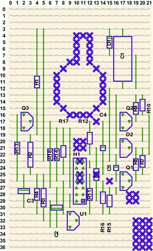
Second Results
This section highlights the changes that were made to the original design, including what happened when it was discovered that the PCB would not fit into the meter box when built.
| Strip board overlay-ed with original Printed Circuit Board and outline of box | Print out of Strip board Only |
|---|---|
 |  |
| Components being added | Completed Board |
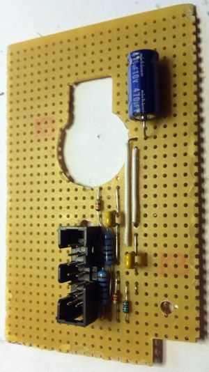 | 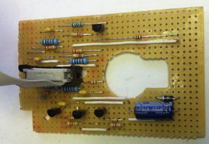 |
New box with circuit board and meter fitted | |
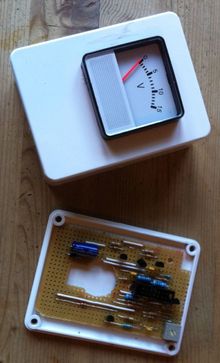 | |
| Terminals, Power Socket and Switches added | |
 | 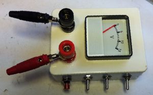 |
This time around
- the full version of VeeCAD has been used.
- Colour overlays are now produced.
- A larger strip board than the original Printed Circuit Board has been used
- Components are placed away from the fixing holes and the rear of the meter
- All the connections to the board are made using the 14 way Header connector H1 in the centre of the board.
Wire Loom Plan
It has been decided to connect to the strip board via an IDC plug and socket. The order of the wires need to be planned so that they are grouped to the external part. Pin 1 is shown on the drawing at the bottom. The wire colour will be noted when I receive the cable.
Funtion | Wire | Colour | Pin | EXTERNAL PART | Length |
|---|---|---|---|---|---|
| M1 | 14 | METER | |||
| M2 | 13 | METER | |||
| OUT | 12 | S1 S2 | |||
| OUT | 11 | S1 S2 | |||
| S1 | 10 | 1 | SW1 | ||
| S2 | 9 | 2 | SW1 | ||
| S3 | 8 | 3 | SW1 | ||
| 2K2 | 7 | 4 | Change Over | ||
| 0v | 6 | 5 8 | Change Over | ||
| 0v | 5 | 5 8 | Change Over | ||
| 0v | 4 | K1 | Power In | ||
| 0v | 3 | K1 | Power In | ||
| Vcc | 2 | K1 | Power In | ||
| Vcc | 1 | K1 | Power In |