Using a Battery Tester using the meter and the case
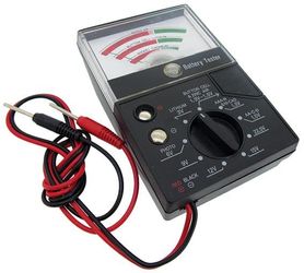
I got a Battery Tester from Cousins. Costs just under £10, has a meter, switch and case. I thought that this be a good starting point, but it was found that this unit was too small to use in the end. A larger box and meter was used in the final version.
https://www.cousinsuk.com/catalog/equipment/battery-watch-testing
The switch is unsuitable.
The circuit of the tester follows:-
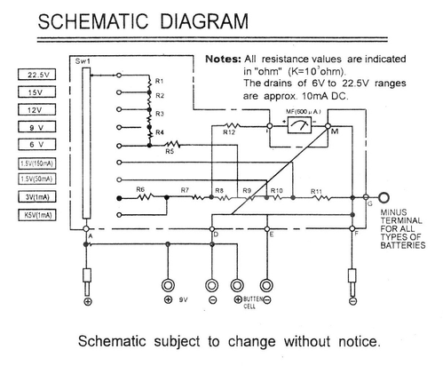
Resistor values are not given in the circuit diagram. They are as follows:-
| R No | Value K | Value | ||||
|---|---|---|---|---|---|---|
| 1 | Grey | Green | Brown | Silver | 0.749 | 850 |
| 2 | Orange | Black | Brown | Silver | 0.302 | 300 |
| 3 | Orange | Black | Brown | Silver | 0.302 | 300 |
| 4 | Orange | Black | Brown | Silver | 0.297 | 300 |
| 5 | Yellow | Violet | Brown | Gold | 0.470 | 470 |
| 6 | White | Brown | Brown | Silver | 0.916 | 910 |
| 7 | Brown | Green | Red | Gold | 1.485 | 1500 |
| 8 | Brown | Orange | Red | Silver | 1.334 | 1300 |
| 9 | Brown | Red | Brown | Silver | 119 | 121 |
| 10 | Red | Black | Black | Gold | 0.020 | 20 |
| 11 | Brown | Black | Black | Silver | 0.010 | 10 |
| 12 | Blue | Grey | Brown | Gold | 0.674 | 690 |
The parts that I thought would be used are the
- Meter
- Lead with Probes
- Size of PCB 45 x 55 mm - strip-board replacement.
- Case
All other parts are removed. There is sufficient depth for mounting switches along the side.
Second Results
This section highlights the changes that were made to the original design, including what happened when it was discovered that the PCB would not fit into the meter box when built.
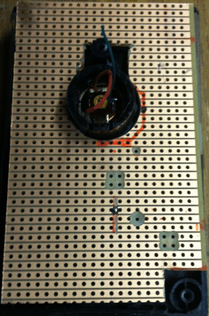
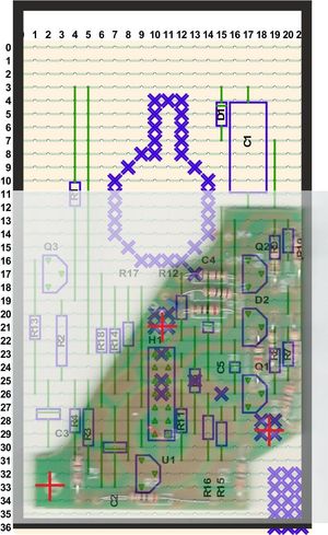 | 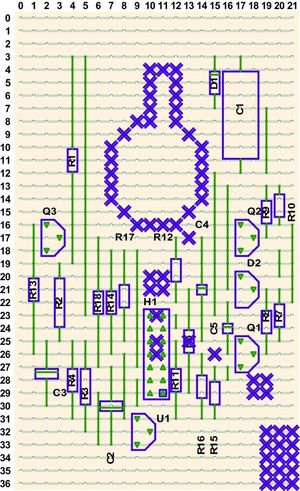 |
| Strip board overlay-ed with original Printed Circuit Board and outline of box | Print out of Strip board Only |
|---|---|
 | 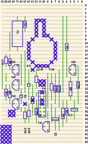 |
Cut the Strip board using the correct side | Track-side Reverse Print out of Strip board Only |
 | |
| Cut the Strip board using the correct side (This is the track side) | Track-side Reverse Print out of Strip board Only |
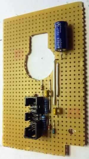 | 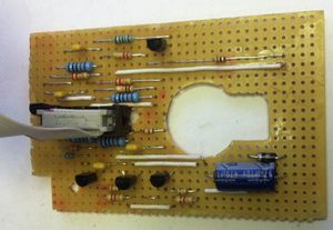 |
| Components being added | Completed Board |
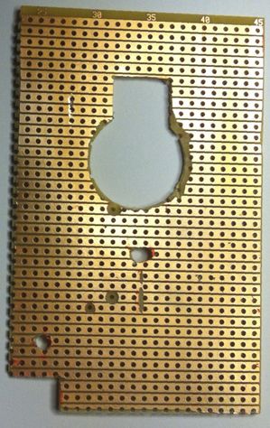
 |  |
| View of 1:1 paper printout of layout. Hole cut out for the meter Component side | Front of the meter with components removed. |
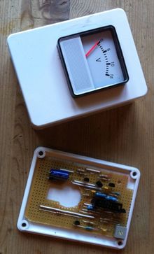 | |
| New box and meter fitted | |