...
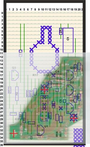
| Strip board overlay-ed with original Printed Circuit Board and outline of box | Print out of Strip board Only |
 | 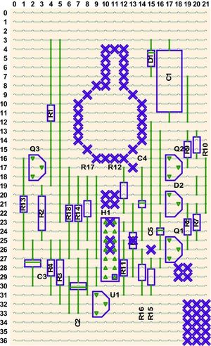 |
Cut the Strip board using the correct side | Track-side Reverse Print out of Strip board Only |
|---|---|
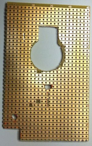 | 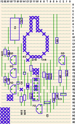 |
| Cut the Strip board using the correct side (This is the track side) | Track-side Reverse Print out of Strip board Only |
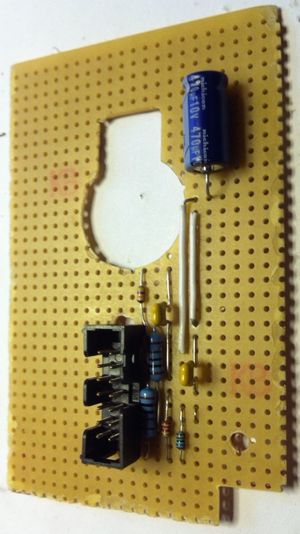 | 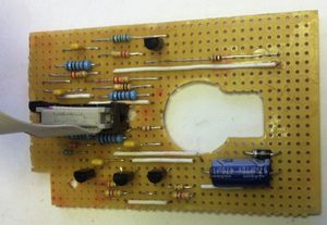 |
| Components being added | Completed Board |
| View of 1:1 paper printout of layout. Hole cut out for the meter Component side | Front of the meter with components removed. |
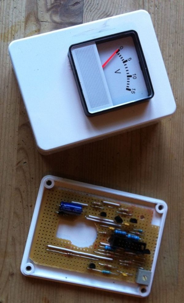 | |
| New box with circuit board and meter fitted | |
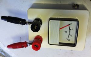 | 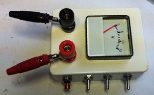 |
| Terminals, Power Socket and Switches added | |
This time around
- the full version of VeeCAD has been used.
- Colour overlays are now produced.
- A larger strip board than the original Printed Circuit Board has been used
- Components are placed away from the fixing holes and the rear of the meter
- All the connections to the board are made using the 14 way Header connector H1 in the centre of the board.
...