...
This section highlights the changes that were made to the original design, including what happened when it was discovered that the PCB would not fit into the meter box when built.
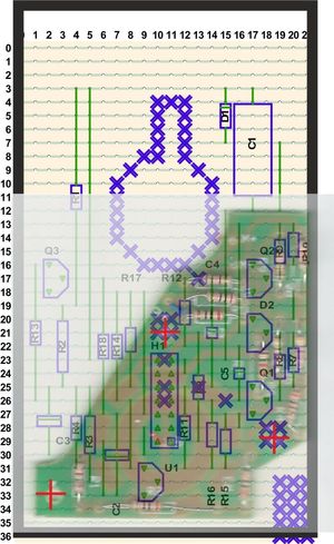
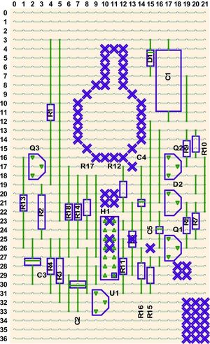
| Strip board overlay-ed with original Printed Circuit Board and outline of box | Print out of Strip board Only | |
|---|---|---|
 |  | |
Cut the Strip board using the correct side | Track-side Reverse Print out of Strip board Only | |
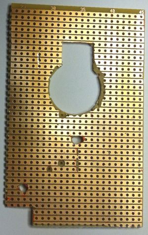 | 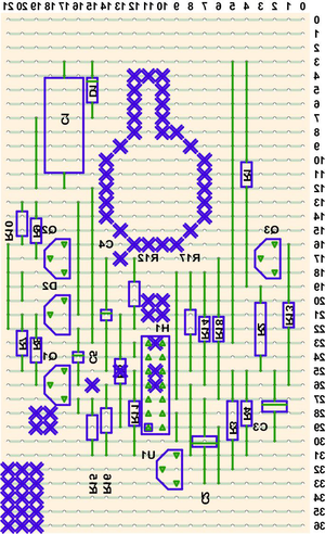 | |
| Cut the Strip board using the correct side (This is the track side) | Track-side Reverse Print out of Strip board Only | |
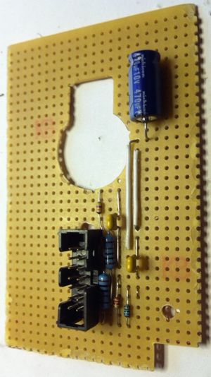 | 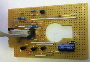 | |
| Components being added | Completed Board | |
| View of 1:1 paper printout of layout. Hole cut out for the meter Component side | Front of the meter with components removed. | |
 | ||
| | |
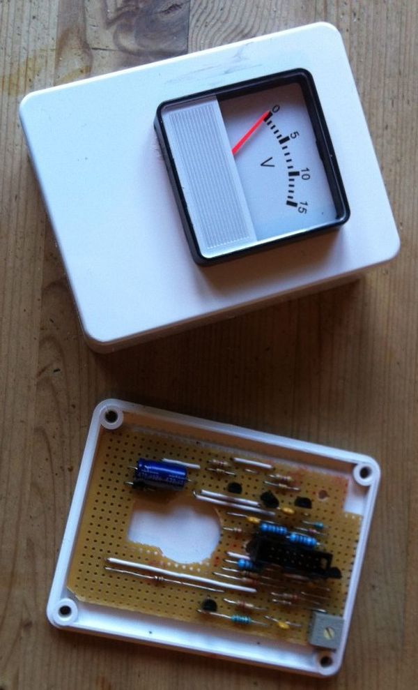
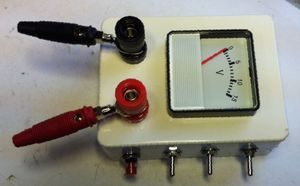
New box with circuit board and meter fitted | ||
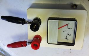 | | |
| Terminals, Power Socket and Switches added | ||
|  | |
This time around
- the full version of VeeCAD has been used.
- Colour overlays are now produced.
- A larger strip board than the original Printed Circuit Board has been used
- Components are placed away from the fixing holes and the rear of the meter
- All the connections to the board are made using the 14 way Header connector H1 in the centre of the board.
...